

Scalextric Le Mans 24 Slot Car Set Learn how to Create Your Own Slot Car Video
Please visit our affiliated websites! |
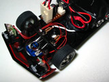
How to Produce a Slot Car Video Fitting the Camera In Taking the camera apart I found the cable into it actually has three connections and not two from the battery as I expected. (PICTURE A) A little prodding with the multimeter reveals the three wires are the +ve and -ve from the battery but there is also an additional +5v line. It seems the bulky connector is also providing an extra +5v supply for the camera from the 9v battery. Since I wanted to lose the connector I had to make a small circuit to provide the 5v line. This is easily done with a 5 volt voltage regulator. I put the circuitry for this onto a small circuit board (seen here next to the battery and the DC power connector. I also added small connectors to plug in the battery, camera and an additional circuit.
The additional circuit board seen here on the right (PICTURE A) is a small FM audio transmitter. The camera
itself has no sound but I really wanted to hear the sound of the motor since that came though so
well with my camera phone. This is a tiny 2 transistor transmitter designed to be very stable.
Since the microphone (the small silver cylinder near the camera) is so close to the motor I was
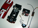
able to leave out the audio amplifier stage to keep the circuit smaller. This shows how everything but the camera fits onto the chassis. (PICTURE B) The black tape is car wiring loom tape rather than normal PVC tape which tends to go sticky over time. The audio transmitter is on top of the battery and taped down. The microphone sits just behind the motor. By having the mic connected to long wires I could position it so that it is held clear of the chassis or motor. This gets rid of any loud knocking or clunking sounds you would hear if the mic body hit any part of the car when it is moving.  PICTURE B (click to enlarge) I also reworked the grille and headlights. I carefully removed the circuit board and cut out the centre section. I resoldered the small SMD resistors onto the legs of the LEDs and added the thin wires which connect to the pickup that concects the car to the track. I also cut out the centre of the grille. The two remaining ends with the lights are held together by the chrome bumper. The reworked LED circuit boards are held in position with a small blob of hot melt glue. The camera which is attached to the body sits just behind the front axle when the body is attached. The camera lens sits just over the axle itself. It is possible to adjust the camera focus by turning the lens by reaching in through the grille with a small tool.
|
|||||


