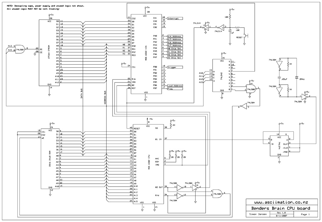
This is the circuit for the CPU part of the brain. For the sake of clarity I have not shown the decoupling capacitors across each IC or all the unused logic gates. Any unused logic needs to have it's inputs tied either high or low to avoid odd things happening in the circuit. Floating inputs are bad! I have also left off the details of the power supply. I used a LM2940 Low Dropout regulator to give me a stable 5 volt supply. The input can be from a wallplug pack or from 4 D cells. Remember I am not an electronic engineer so this circuit may not be optimal. It does work though!
It is based rather heavily on the original 1541 disk drive circuit. I simply took off the bits I didn't need such as the second VIA, second ROM and all the I/O circuitry and added my own clock and manual reset circuit. I also used a 27C64 EPROM. The original drive uses two 2364 devices which are impossible to get now.
One thing people may wonder about is the flip-flop between the CPU and clock generator on the right hand side of the diagram. That is a clock divider circuit which I had to use since the CPU I have is a 1Mhz device and all I could get locally were 2Mhz clock crystals!

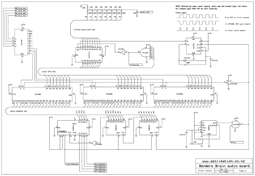
Below is the circuit for the audio part of the brain. The circuit is a little convoluted I guess and there are definitely much easier ways to do this but I was making use of the parts I had easily available. Basically a timer drives a binary counter which then addresses bits out of whichever ROM chip is selected by the CPU at the time (I could have up to ten but I only used three). The top four bits of the counter (A14 - A17) are presettable by the CPU and these are set just before a play starts. Setting the address also resets the two lower bit counters back to zero. Using these top four bits means the memory is effectively split into pages with each page start being addressable using these bits. The samples are stored starting on a page boundary so the CPU can start playing at the beginning of each sample. The samples may be longer than one page in length. To detect when to stop playing I encoded at the end of each sample the maximum 8 bit value, 255, and I detect when all the output bits go high with an 8 input NAND logic gate. This causes and interrupt signal to the VIA which then interrupts the processor which knows it should stop playing. The audio is converted from digital to analogue with a simple R-2R ladder. This provides good enough audio quality for the simple speech I am playing. I use a LM386 on the audio board as a small amplifier. The clock is a simple 555 timer based circuit which runs all the time. The clock signal is gated to the rest of the circuit by the CPU. When a play finishes the clock signal is switched off stopping the play and we simply wait for another play trigger input.

Below is the 6502 assembly language. Again I am not a professional software engineer. Actually, I am, but not in 6502 assembly language. This was my test code and first real 6502 assembly language program so again it might not be efficient or pretty but it does the job. I did that thing all software engineers will know about. I said I'll do a prototype then rewrite it once I know how it works. Of course we'll never ship with that prototype code.....
rom_start    = $E000           ; Start of ROM memory
reset        = $FFFC           ; Reset vector
interrupt    = $FFFE           ; Interrupt vector
via          = $1800
via_b        = via + $0        ; VIA port b
via_a        = via + $1        ; VIA port a
via_bdir     = via + $2        ; VIA port b direction 1 = output
via_adir     = via + $3        ; VIA port a direction 1 = output
via_pcr      = via + $C        ; VIA peripheral control register
via_ier      = via + $E        ; VIA interrupt enable register

chipsam      = $07FE           ; Store the chip and sample to play
playing      = $07FF           ; Are we currently playing flag


        .ORG rom_start


;Initilisation
        LDA    #$FE            ; Load ACC with b11111110
        STA    via_bdir        ; Set VIA port b all output except b0 input
        LDA    #$FF            ; Load ACC with b11111111
        STA    via_adir        ; Set VIA port a all output

        LDA    #$CC            ; Load ACC with b11001100 - PCR
        STA    via_pcr         ; Set VIA PCR for CA2, CB2 held low, CA1, CB1 high->low transition

        LDA    #$82            ; Load ACC with b10000010 - IER
        STA    via_ier         ; Set VIA IER for CA1 active

        LDA    #$00            ; Clear the playing flag
        STA    playing

        CLI                    ; Enable interrupts

; Simply loop around storing each samples location in memory.
; Then poll to see if we were triggered to start playing.

loop

c1s1    LDA    #$00            ; Data b0000 0000 - CHIP SELECT/ADDRESS
        STA    chipsam         ; Store data - chip 1, address 0000
        JSR    poll
c1s2    LDA    #$02            ; Data b0000 0010 - CHIP SELECT/ADDRESS
        STA    chipsam         ; Store data - chip 1, address 0010
        JSR    poll
c1s3    LDA    #$06            ; Data b0000 0110 - CHIP SELECT/ADDRESS
        STA    chipsam         ; Store data - chip 1, address 0110
        JSR    poll
c1s4    LDA    #$07            ; Data b0000 0111 - CHIP SELECT/ADDRESS
        STA    chipsam         ; Store data - chip 1, address 0111
        JSR    poll
c1s5    LDA    #$08            ; Data b0000 1000 - CHIP SELECT/ADDRESS
        STA    chipsam         ; Store data - chip 1, address 1000
        JSR    poll
c1s6    LDA    #$0A            ; Data b0000 1010 - CHIP SELECT/ADDRESS
        STA    chipsam         ; Store data - chip 1, address 1010
        JSR    poll
c1s7    LDA    #$0C            ; Data b0000 1100 - CHIP SELECT/ADDRESS
        STA    chipsam         ; Store data - chip 1, address 1100
        JSR    poll

c2s1    LDA    #$10            ; Data b0001 0000 - CHIP SELECT/ADDRESS
        STA    chipsam         ; Store data - chip 2, address 0000
        JSR    poll
c2s2    LDA    #$15            ; Data b0001 0101 - CHIP SELECT/ADDRESS
        STA    chipsam         ; Store data - chip 2, address 0101
        JSR    poll
c2s3    LDA    #$17            ; Data b0001 0111 - CHIP SELECT/ADDRESS
        STA    chipsam         ; Store data - chip 2, address 0111
        JSR    poll
c2s4    LDA    #$19            ; Data b0001 1001 - CHIP SELECT/ADDRESS
        STA    chipsam         ; Store data - chip 2, address 1001
        JSR    poll
c2s5    LDA    #$1D            ; Data b0001 1101 - CHIP SELECT/ADDRESS
        STA    chipsam         ; Store data - chip 2, address 1101
        JSR    poll

c3s1    LDA    #$20            ; Data b0010 0000 - CHIP SELECT/ADDRESS
        STA    chipsam         ; Store data - chip 3, address 0000
        JSR    poll
c3s2    LDA    #$23            ; Data b0010 0011 - CHIP SELECT/ADDRESS
        STA    chipsam         ; Store data - chip 3, address 0011
        JSR    poll
c3s3    LDA    #$25            ; Data b0010 0101 - CHIP SELECT/ADDRESS
        STA    chipsam         ; Store data - chip 3, address 0101
        JSR    poll
c3s4    LDA    #$2B            ; Data b0010 1011 - CHIP SELECT/ADDRESS
        STA    chipsam         ; Store data - chip 3, address 1011
        JSR    poll
c3s5    LDA    #$2D            ; Data b0010 1101 - CHIP SELECT/ADDRESS
        STA    chipsam         ; Store data - chip 3, address 1101
        JSR    poll
c3s6    LDA    #$2E            ; Data b0010 1110 - CHIP SELECT/ADDRESS
        STA    chipsam         ; Store data - chip 3, address 1110
        JSR    poll

        JMP    loop

; Polling subroutine. In here we check if the button is pressed (portb 0 == 0)
; and if so start playing the currently stored sample.

poll
        LDA    playing         ; Check if we are playing
        AND    #$01            ; 1 == playing
        BNE    return          ; We are playing so just keep looping

        LDA    via_b           ; Not playing so check VIA port b
        AND    #$01            ; Check portb 0 == 1 (button NOT pushed)
        BEQ    play            ; No button is down, start playing
        JMP    return          ; Button NOT pressed so return
play
        LDA    chipsam         ; Retrieve the chip and sample data
        STA    via_a           ; Push it to the VIA port a

        LDA    #$40            ; Data b0100 0000 - Reset and load
        STA    via_b           ; Load data on port b
        LDA    #$80            ; Data b1000 0000 - Start playing
        STA    via_b           ; Load data on port b

        LDA    #$01            ; Set the playing flag
        STA    playing

        LDA    #$82            ; Load ACC with b10000010 - IER
        STA    via_ier         ; Set VIA IER for CA1 interrupt active

return
        RTS                    ; Return

; Interrupt service routine. this is triggered when the 6522 VIA interrupts
; at the end of a sample. We store the ACC, clear the interrupt. We reset the
; audio board by clearing port a, resetting the counters and stopping the play.
; Then reset the playing flag, restore the ACC and continue.

isr
        PHA                    ; Store the accumulator

        LDA    #$02            ; Load ACC with b00000000 - IER
        STA    via_ier         ; Clear VIA IER for CA1

        LDA    #$00            ; Reset port back to zero
        STA    via_a           ; Push it to the VIA port a
        LDA    #$40            ; Data b0100 0000 - Reset and load
        STA    via_b           ; Load data on port b
        LDA    #$00            ; Data b0000 0000 - Stop playing
        STA    via_b           ; Load data on port b

        LDA    #$00            ; Clear the playing flag
        STA    playing

        PLA                    ; Retrieve the accumulator
        RTI                    ; Return back to looping through samples

        .ORG reset             ; Reset vector
        .WORD rom_start

        .ORG interrupt         ; Interrupt vector
        .WORD isr